
CNG Skids Ice Up in Winter: Why, and How Much Heat It Needs
Icing is not an equipment fault. It is two certainties meeting: drop the pressure and the temperature falls, and the gas always carries water. Here is the 79 °C drop behind a 24.6 MPa letdown, the three points that freeze first, what frost position tells you, why a 2,000 Nm³/h skid needs about 60 kW of heat, and the four questions to ask a supplier.
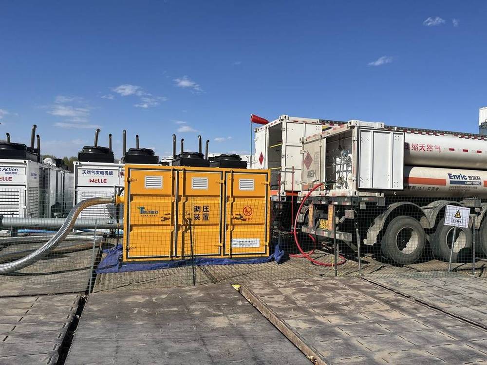
Field installation: pressure-reducing unit and CNG trailer (photo)
All temperature drops and heat duties below are worked examples based on the assumptions stated, shown to fix the order of magnitude. A real project is settled against its design documents, gas composition report and process calculation. Dew-point limits and gas-quality requirements follow the standard version currently in force and the contract.
Every November the phone starts ringing about ice blockage. So here is the conclusion first.
Icing is not a quality problem with the equipment. It is two certainties arriving at the same moment: drop the pressure and the temperature must fall; and the gas always carries water. Put those two together and, once the temperature crosses zero, ice will form somewhere narrow. The only variable is whether it blocks at the regulator seat, at the pilot, or in the filter element this year.
Below, the two are calculated separately. Once you have run both, you will know whether your skid is short of heat or short of gas quality.
1. Start with the temperature drop: 24.6 MPa of letdown, about 80 °C
Taking natural gas from 25 MPa down to 0.4 MPa is not a slow release of pressure. It is throttling.
Throttling is close to adiabatic and isenthalpic: the gas expands abruptly through the seat, does work as its volume grows, and that work can only come out of the gas's own internal energy — so the temperature falls with it. This is the Joule–Thomson effect.
There is a rough field figure for the high-pressure section above 20 MPa: about 3 to 5 °C of temperature drop per 1 MPa of pressure drop.
Using the conservative end, 3.2 °C per MPa: total letdown 25 − 0.4 = 24.6 MPa; total drop 24.6 × 3.2 ≈ 79 °C.
In other words: with a 15 °C inlet in summer, the gas leaves the seat at about −64 °C. With a 5 °C inlet in winter, about −74 °C. This is not "it might freeze". Every temperature condition needed for ice is already met.
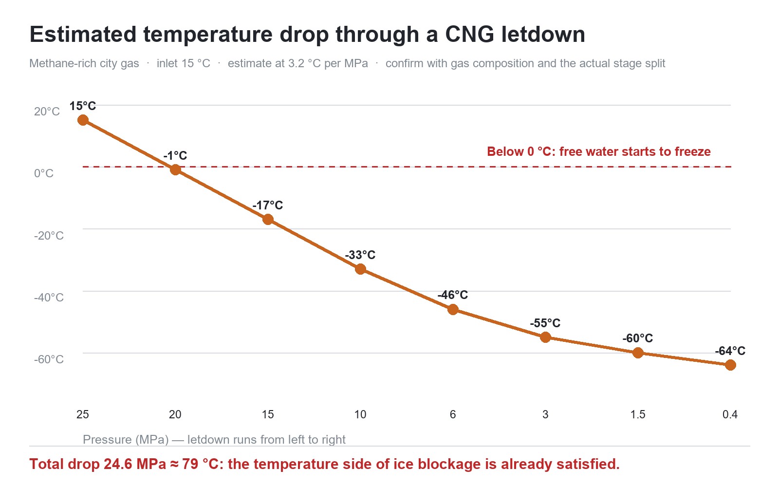
Temperature drop estimated at 3.2 °C per MPa (illustrative)
One caveat. The 3 to 5 °C per MPa figure is a field rule of thumb. The accurate value comes from a process calculation using the pressure split, the gas composition and the inlet temperature. Where CO₂ or nitrogen run high, the Joule–Thomson coefficient differs and the drop changes. The order of magnitude does not: from 25 MPa to 0.4 MPa it is always in the seventy-to-eighty-degree range.
2. Where the water comes from: three sources, each more common than the last
A sub-zero temperature is only the precondition. There also has to be water. In natural gas it comes from three places:
- Incomplete dehydration at the source. Gas-quality standards set a water dew point, but trailer loading, temporary supply and wellhead gas all fluctuate in practice.
- Water left in equipment and piping. Cylinder swaps, maintenance, rain ingress and storage banks left idle for long periods all introduce free water.
- Poor purging and drying after construction or pressure testing. The most commonly skipped item on a new station: test water stays at the low points and keeps working its way out all winter.
There is only one criterion: if the water dew point is above the post-throttling temperature, water will condense out.
And one effect that confuses people: in the high-pressure section the skid can block before the temperature reaches 0 °C. What blocks it is a hydrate — a clathrate compound of water and gas formed at high pressure and low temperature. It looks like ice, is not pure ice, plugs harder and melts more slowly. So the answer to "it is not even below zero, how can it be blocked" is: hydrate.
3. Below zero, three places freeze first
The same amount of water does not block everywhere. The narrower the passage and the larger the temperature drop, the sooner it freezes. On a skid it is almost always these three:
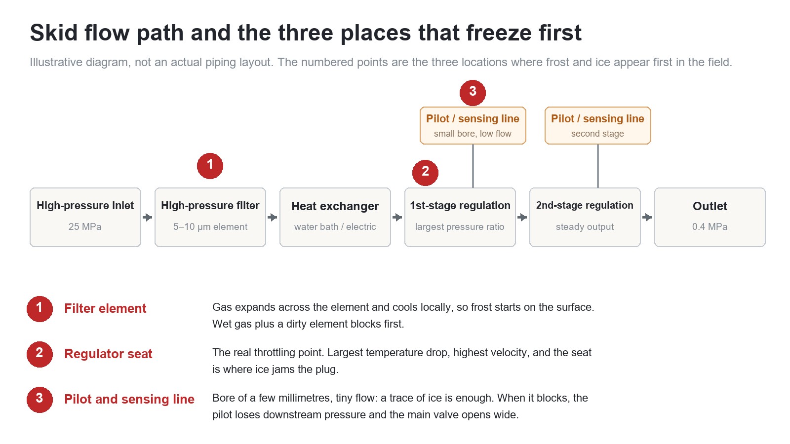
Skid flow path and the three first freeze points (illustrative)
1. The filter element. Element pores are measured in microns. As gas passes through it expands locally and cools, so the surface runs coldest. With wet gas and a loaded element, frost starts on the surface, then seals the whole element and the differential pressure climbs fast.
2. The regulator seat. The actual throttling point. Largest temperature drop, highest velocity. Ice jams the plug here, the opening can no longer move, and the outlet pressure starts to wander.
3. The pilot and its sensing line. Sensing lines are typically only a few millimetres in bore with very little flow, so a trace of ice closes them. Once closed, the pilot no longer sees true downstream pressure and the main valve keeps opening. This is the most dangerous form of icing, because the symptom is not "no gas" — it is rising outlet pressure, possibly overpressure.
4. Where the frost is, is where the fault is
No dismantling needed on site. Look at where the frost sits, then at which way the gauge moves:
- Frost on the lower half of the valve body, near the seat; outlet pressure swinging up and down → the seat is iced and the opening is out of control.
- Frost on the pilot and sensing line; outlet pressure rising, possibly overpressure → the pilot has lost its signal and the main valve is held open.
- Frost on the filter housing; differential pressure up, flow down → the element is iced over and the open area has shrunk.
- Frost over most of the skid; outlet temperature below 0 °C → not enough heat input, and not a local problem.
The order matters: read the frost position first, then the direction of the pressure. Pressure falling usually means the seat or the element. Pressure rising means check the pilot and sensing line first.
5. How much heat is actually needed: about 60 kW for 2,000 Nm³/h
Many skids are not short of heating. They are short of heat duty. The power can be estimated with the plainest of formulas: Q = mass flow × specific heat at constant pressure × temperature rise.
Take a 2,000 Nm³/h skid, gas density 0.72 kg/Nm³: mass flow 2,000 × 0.72 = 1,440 kg/h ≈ 0.4 kg/s; cp taken as 2.3 kJ/(kg·K); raising the gas from −60 °C to +5 °C gives ΔT = 65 K.
Q = 0.4 × 2.3 × 65 ≈ 60 kW. Add a 1.3 safety margin and the installed duty should be 75 to 80 kW.
That number settles one thing: on a 2,000 Nm³/h skid, a few heat-tracing tapes will not lift the gas from −60 °C to above zero for a whole winter. Tracing tape insulates and protects a valve body locally; it cannot deliver tens of kilowatts of heat transfer.
The three heating options do different jobs:
- Electric heat tracing: local frost protection on valve bodies and sensing lines. Low power, insulation only.
- Electric heat exchanger: small to medium flows, fast response, unattended operation — but higher electricity cost and demanding hazardous-area electrical certification.
- Water-bath heat exchanger: large flows, continuous supply, stable outlet temperature — but it needs a hot-water source or boiler, and scaling has to be managed over the long term.
One point that is routinely missed: heat must be added before the throttling point or between stages. Adding it to the outside of the valve body is only insulation. If the heat never reaches the valve cavity, the seat still runs at −60 °C.
For exchanger selection, see water-bath vapourisers and heat exchangers; for the full skid configuration and sizing logic, see CNG pressure-reducing skids.
6. Four common misconceptions
One: with tracing tape fitted, it cannot block. Tracing tape keeps the outside free of frost. It does not fix gas that is too cold. What decides blockage is the gas temperature and water content before the seat.
Two: just raise the inlet temperature. Trailer gas temperature is set by the cylinders and the ambient conditions; it cannot be raised reliably on site. What you can control is heat exchange, not source temperature.
Three: the larger the heat-transfer area, the better. Area is sized for maximum flow plus the local minimum ambient temperature, and it must allow for the degradation caused by frost. Oversizing costs money, and on a water bath it brings scaling and slow warm-up.
Four: deal with it once the frost appears. Icing is calculated, not repaired. The tens of degrees missed at design stage are paid back over an entire winter in operation.
7. Four questions to put to the supplier
- What minimum inlet pressure is it designed for? A trailer runs down as it empties. Capacity is verified at the minimum inlet pressure, not at 25 MPa.
- What is the spread between maximum and minimum hourly flow? The turndown ratio decides whether it will cycle and locally overcool at low flow.
- What is the water dew point of my gas? This single figure sets the heat duty. Fixing a heating power without a dew point is sizing blind.
- How are the heating method, temperature control and explosion protection configured? In a hazardous gas area, electrical certification, over-temperature protection and fault alarms all belong in the specification.
8. One last line
Icing is never a fault that suddenly appears in winter. It is a result written at design stage.
The temperature drop is physics and cannot be changed. The water content comes from gas quality and workmanship, and can be managed. The heat duty comes out of a sizing calculation, and must be calculated. Get any one of the three wrong and this winter will hand it back to you at some early hour, at a seat running at −60 °C.
To have it checked against your own duty, send the flow rate, minimum inlet pressure, outlet pressure, gas water dew point and the local extreme minimum temperature. Engineering returns a heat duty and configuration against those five parameters.
Written by the Tairan engineering team from project records and standard documents. Please cite the source when quoting.